


What is technical drawing and how does it impact the technical writing process? Read on to learn more.
This guest blog post was written by Antoni Dzumaga, an experienced technical writer with broad-ranging skills and experience in software, digital marketing & data analysis, electronics, and engineering sectors, specialising in technical documentation and illustration.
He has 25 years of experience as a technical author. In his last role for Apteco Ltd, he used MadCap Flare to Single-Source output to online help and PDFs. He modernised the documentation catalogue to the corporate standard, including installation guides, API integration guides and software architecture diagrams.
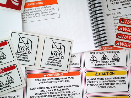
Technical drawing or technical illustration is the use of detailed illustrations to provide a visual representation of technical information. It is also a safety or legal requirement for specific products.
In the 19th century, technical drawing tools such as mechanical pencils, technical pens, T-squares, rulers, compasses, drawing boards, and erasers were widely used. These tools enabled engineers and architects to create accurate and detailed drawings with precision and ease.
Today, CAD software allows for even greater accuracy and speed, making it an indispensable tool in the modern-day engineering and design world to make illustrations, working drawings, and schematics.
These illustrations are used in technical documents to explain complex concepts, processes, or products in an easy-to-understand way. They typically include diagrams, schematics, exploded views, cutaways, and 3D renderings to help the reader better understand the subject.
Some technical illustration types include computer-aided design (CAD), illustration, infographics, and information design.
Technical Drawing and Illustration
Technical drawing tools for CAD, like AutoCAD, SolidWorks, ISODraw, and VectorWorks, to name a few, are essential for use in the aerospace, mechanical and electrical engineering, and automotive industries. As technical writers, we apply the same skill to extract the necessary level of detail from engineering drawings as we do in producing technical content.
Technical drawing and illustration applications are vector based. What does that mean?
A vector-based application is a technical drawing software program that creates images using mathematical equations to represent lines, shapes, and colours. In contrast, raster- based applications like Adobe Photoshop create images using a grid of individual pixels.
A vector-based application stores the image information as a series of mathematical formulas that define the lines, curves, and other elements, which allows scaling up or down without losing quality.
In addition to scalability, vector-based images offer other advantages, such as the ability to easily edit individual elements of the illustration and output the image in various file formats.
Vector-based applications like Adobe Illustrator, Affinity Designer, and Inkscape are best for creating precise and detailed illustrations that require high accuracy and precision, such as technical drawings, diagrams, infographics, and schematics.
These applications are beneficial for creating graphics, making them ideal for use in technical documentation. Additionally, these applications offer a range of tools and features for creating complex graphics, such as the ability to manipulate curves and shapes, apply gradients and patterns, and add text and labels, making them versatile and powerful tools for creating technical illustrations.
Infographics are visual representations of data and information designed to be easily understood by a broad audience. They often combine charts, graphs, and other visual elements to convey complex data and engagingly.
Overall, these visual representations should convey complex information in a way that is easily digestible and understandable for their intended audience. They require a combination of design and technical skills to create.
Information Design
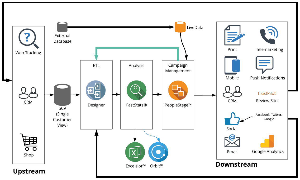
Information design is using visual tools to communicate complex information clearly and understandably. In the context of software documentation and architecture, information design can help developers and stakeholders better understand the structure and functionality of an application.
Writing is hard. And scaffolding is essential to support this challenging activity.
Using an information design to create flowcharts and dataflow diagrams can help writers organise mental reasoning by offloading aspects of thought onto the tool. This makes thinking and elements of the activity visible. Planning that focuses on text structure hence we can write more effective texts.
Tools like Lucidchart, and Microsoft Visio, are just a few. There are many cloud- based tools available specifically designed to document software architecture.
SVG in Technical Documentation
The vector-based nature of technical illustration applications and web-based tools means understanding the use of Scalable Vector Graphics (SVG) is an essential skill to learn, we are encouraged to use snippets and variables in our content, and just like those, SVG are reusable, easily edited with a simple text-based application and can be modified with CSS.
You can take a corporate brand guide and create a library of assets for an HTML5 responsive help project, social branding that uses styles to control the SVG, and responsive social graphics that resize to the device.
There’s a compelling case for developing a workflow that uses SVG; the time- saving and versatility it offers me means I have to work less, and they look great.
Common Applications for Technical Drawing
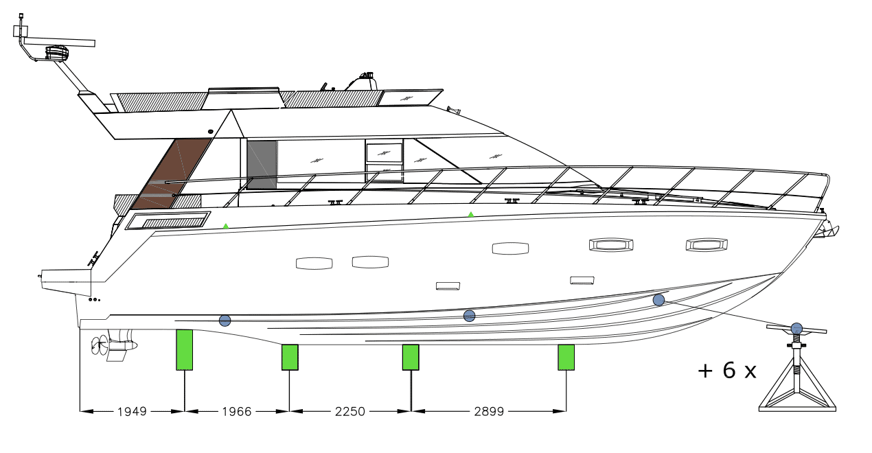
Some of the most common applications that require technical drawing skills include: mechanical drawing, assembly drawing, working drawings, architectural drawings, and detail drawings.
Mechanical drawing is another application of technical drawing, which involves the design and development of mechanical components and systems. Technical drawing is used in mechanical drawing to create detailed drawings of parts and assemblies, including exploded views, section views, and assembly instructions. They also aid in CNC machining.
Working drawings provide instructions for the construction or assembly of a product or structure. Working drawings can be used to create detailed drawings of building components, such as plumbing, HVAC, and electrical systems.
Architectural drawings are used in the design and construction of buildings. They are used to create floor plans, elevations, and detailed construction drawings of buildings.
Detail drawings are technical drawings that provide detailed information about a specific part or component. They are used to create precise and accurate representations of parts, including dimensions, tolerances, and materials.